Sunday, November 28, 2010

Week Ending Nov. 28 2010

This week has been very successful.

We completed all the engineering drawings and finalized the solid model for the design review.

Also, the assembly of the MCM went (relatively) smoothly.  It was very satisfying to see our creation work after spending so long designing it!

Here are some pictures of this week's events:

Assembled MCM with control electronics (not in final location) 
Notice yellow hosing used to connect motor to shaft


View of toggle arm
There are small things we need to fix on the MCM:
     1.  Add velcro to the bottom (after final waterjet cuts)
     2.  Lengthen control wires to make room for rear scoring arm
     3.  Fix side-to-side movement of toggle arm on axle.  There are a few options for this:
              a.  Epoxy the gear to the shaft and the set screw in place (messy and permanent, not good practice).
              b.  Make a new shaft that will press-fit into the worm gear (time consuming, uses more material).
              c.  Drill a small hole in the current shaft that the worm gear will extend in to.  This should prevent  
                   side-to-side motion even if the set screw loosens a bit.

The first and second items can be taken care of Monday in lab (or as soon as the water jet cut is made).  The final item can be decided on Monday in lab and fixed depending on the decision.

On a different note, here is our updated schedule from here to the end of the semester:
http://goo.gl/pJqtu

And our updated to-do list:
http://goo.gl/90Hrp

I'll leave you with a video of our MCM in operation:

Sunday, November 21, 2010

Week Ending Nov. 21 2010

Here's an overview of our progress this week:

Unfortunately the shop had to close early on Thursday so we didn't get as much done as we'd hoped.  Then on Friday in the shop something went awry when making the side pillows for the MCM and the axle holes are two hundredths too high.  To fix this we have two options:

A.  Restart and make two new pillows.

B.  Shave the bottom of the pillows to effectively lower the holes.

In the name of time we're going to try option B tomorrow in the shop.  Assuming that goes well we'll be ready to assemble the baseplate of the MCM.

On a brighter note here are some of the parts that we've completed thus far:

The base plate with the MCM holes prior to counterboring.

The front motor mount.

The side pillows.

The worm gear in the toggle arm.

Stephen hard at work.

The chassis as of Wednesday.  The side pillows will be located over the side holes.

Also this weekend, we have completed the SolidWorks module for the entirety of the SlotBot.  The scoring arm structure has been finalized as well as the cart module.

This week will be a push to get all of the parts completed, but from here on out it is a straight shot since all the design work is complete.

Sunday, November 14, 2010

Update for Week Ending 11-13-10

As of the end of this week we have been to the machine shop three times and are preparing to finish the 3 manufactured parts due next Friday.

The toggle arm motor mount has been completed with the exception of the mounting holes.  These will be drilled and counter bored next week.

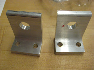
We're changing the mounting process that we're going to use with the pillows in order to make better use of our time.  Previously the plan was to create 3 holes in the base of each pillow, one for a bolt and two for dowel pins.  Since it is going to take too long to get the appropriate precision for the dowel pin holes we are changing the design so each pillow is connected to the base plate via two 1/4-20 bolts.  The current design will look like this:
Front and back pillow

Another component that will be manufactured soon is the base plate.  This will be done on the water jet because it involves lots of holes.  The counter bores for each hole will then be finished on the mill.
Base plate (bottom view to show counterbores)

Finally, a recap of the lessons we learned in the shop this week.  Hopefully this will keep someone else from having these difficulties.

When using the edge finder to zero the x and y co-ordinates after milling a part to size, remember to do two things.  
  1. Take into account the radius of the edge finder itself!  Otherwise measurements will be ~0.1" off.
  2. When re-orienting a part to work on a different aspect of it, remember to re-zero the mill off of the same edge as before!  This edge will likely be in a different location than it was, so be careful.  
That's all for now.  Expect more updates as this week unfolds.

Monday, November 8, 2010

Worm Gear

Good news!  The worm and worm gear came in the mail today.  The teeth aren't as deep as I had expected when I ordered them, but it will still serve it's purpose as long as we are precise in our machining.

Here are some pictures:

The set screws can be seen on the right hand side of each.  They're very small!

Sunday, November 7, 2010

Slot Module Update

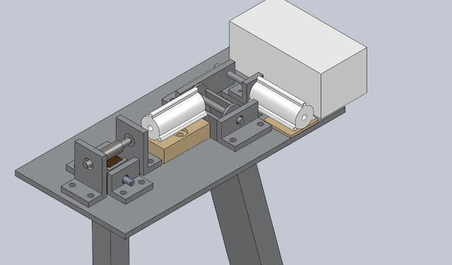
After looking at the original pictures of our slot module (see first post) I've decided to upload some more recent screenshots.
Close-up of the slot module chassis
Here's a quick breakdown of slot module changes:  
  • The control box has been located on the back (the big white box) although the fit is a little tight.  
  • The planetary gearboxes have been located as well (the while cylinders); they sit on wooden risers to make proper alignment with the shafts.  Note that the largest wooden riser in this photo may be replaced with an aluminum one (see previous post).
  • The front and back toggle jam arm pillows are now being made out of a larger piece of angle aluminum to eliminate the wooden risers.  See the next picture.
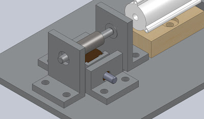
Close of up toggle jam arm pillows
Here the taller front an back pillows are easier to discern.  This ought to be simpler to machine and more accurate over using wooden risers (compare this setup with the original configuration from the first post).  Also in this picture, the worm can be seen as an over sized steel cylinder mounted on the upper shaft.  It contacts the large bronze worm gear that is embedded in the pillow structure.

Another slight modification:  The worm gear is of a larger diameter than the toggle arm is thick, so the upper end of the arm has been cut to allow the gear to protrude from the sides:

The two foreground pillows have been made clear so the inner axle layout and the top end of the toggle arm can be seen.
Notice the bushings on the lower axle and the bearings on the upper.

We'll be heading to the machine shop this week, so expect an update on manufacturing soon!

Saturday, November 6, 2010

MS6 Recap

The engineering for our most critical module turned out well.  We're pleased with our progress so far, but there are some points that we need to take care of looking forward:

1.  Should we replace the wooden toggle arm motor riser with an aluminum block?  In our discussion during MS6 it sounded like the compound wooden block will be challenging to machine.  It may be better to simply buy  an aluminum block of similar dimension and mill it to size.

Breakdown of buying AL versus using wood:
Pros:  Simpler manufacturing
Cons:  Increased cost, possibly increased weight compared to wood.

2.  How will we locate and attach the pillows with the base plate?  There are two options that we are currently considering.

Option one:  Use two bolts for each pillow (this is our current setup).
         Pros:   Simpler to machine, lower tolerances.
         Cons:  Pillows not self-aligning, possibility for "drift" if bolts aren't tight enough.  Poor engineering
                    practice to use threaded fasteners to constrain shear loads.

Option two:  Use two dowels to locate each pillow and a single bolt to hold it down.
         Pros:   Excellent alignment.  Better engineering practice to use dowels to constrain shear loads.
         Cons:  More steps in manufacturing (drilling + reaming).  Slight error in machining could be cause for
                    part rejection.

Dowels pins.  Useful for accurate location of a part.
Source:  


Since machining begins on Monday, we will be making a decision on this in the next few days.  


Thursday, November 4, 2010

Progress up to MS6

We are currently finalizing MS6.  The bill of materials and the manufacturing plan is going well.  A Google doc is proving very useful to allow team collaboration on these documents.

Making the engineering drawings is coming along, but some of the details difficult to nail down.  Certain SolidWorks features (like SmartDimension and title block editing) are finicky and it takes some coercion before the program does what we want of it.

Another issue we're coming up against is tolerancing.  It isn't always clear to us when to use what tolerances, so more reading/research into this subject is needed.  We'll post more as we figure this out.

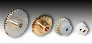
The good news is that our worm and worm gear is in the mail!  The combo gives a 40:1 reduction.  The supplier we used was SDP/SI and we'd definitely buy from them again.  The prices were good (especially compared to McMaster) and there was plenty of variety.  Here are some pictures to give an idea of the parts we ordered (our worm is steel, our gear is bronze):


Tuesday, November 2, 2010

MCM Preparation

For MS6 here are the are the following links:

Step by step manufacturing plan (update as you go):   http://goo.gl/GvlZ

Bill of Materials (update as you go):  http://goo.gl/Bt3X