Sunday, December 12, 2010

Reflection of Adam Stevens

When I enrolled in ME250 earlier this year I was excited to take the class because it had the terms “design” and “manufacturing” in the title.  I have always been a hand-on type of guy so I figured this would be an interesting.

Four months later I can safely say that not only was this an interesting class but it was also an extremely challenging one.  Appropriately, however, the increased challenge came with increased reward.

I learned a lot of different things this semester, more than I could hope to put down on one page.  Here’s a short overview of things that I learned, by topic:

Design and Manufacturing
The funneling design process was a completely new concept for me.  One of the most important lessons I have taken away from this is that the possibility for creativity decreases as the design process advances.  Fortunately my team did well with creativity from the beginning.  Had we not been so thoughtful we would have been quickly caught in a situation where we needed to make changes but were unable to due to the progress that we’d already made.  As for manufacturing, everything in this category was new to me as well.  I focused primarily on the mill, as Stephen already had lots of lathe experience.  Tolerances and the impact they have on design is particularly interesting to me.  At the beginning of the semester I simply designed my parts to call for maximum precision on all dimensions.  I soon realized that to get the tolerances precise is no mean feat and that it is better practice to only tightly tolerance those dimensions that absolutely require it.  From this experience the connection between precision and price in the “real world” is readily apparent.  It now makes sense to me why precision instruments like automatic watches are expensive.

Teamwork and Time Management
I was fortunate to find myself in a very capable team for this project.  Delegation of tasks helped us complete assignments that would have taken a lone worker at least three times as long.  In addition to working well together, we avoided placing blame completely on one group member in the event that something went wrong.  Instead we worked with that person to get it right the next time around.

I could keep going, but length requirements dictate that I move on.

By the way of course improvements, the elimination of vague terminology from grading rubrics would be a big plus.  This was especially evident in Homework 1.  The rubric at one point states that a “nice, clear sketch” is required to earn full credit.  If I’ve ever read a vague statement in a rubric, this is it.  However since Homework 1 was recollected for a grade adjustment this oversight has been largely made up for.

The frequent rule changes were a sticking point for many people and I tend to agree with them that it made the course more difficult.  On the other hand, I also agree with those who say that dealing with changes is good real-world experience.  With that in mind I am okay with the constant revisions, but hopefully the graders of the course will consider this at the end of the semester when making the final curve.

Finally, if I could have done anything to improve my performance in the course I would have helped my teammates learn how to use the mill and SolidWorks earlier.  During the beginning of the machining period I did much of the work while Mack and Clayton helped out.  If I could change this I would get them more involved from the start.  I think this would have increased our productivity as they would have felt more comfortable milling on their own.  I believe that when a teammate has trouble learning how to use a tool it is the responsibility of the team members to teach him.  It’s only recently that I realized this and therefore my teammates suffered.

Reflection of Clayton Parsons


When I first signed up for ME 250 here at U of M I didn’t know what to expect.  Would it be time consuming, boring, hard, frustrating or even fun?  What I discovered is that it had a little bit of all those things and more.
The first thing I really noticed about this class was that it was going to be very free and open.  From my previous classes, I was used to having a professor holding my hand for each step of the class.  It wasn’t long before I began to have an eerie sensation as if someone had told me to go for a bike ride while secretly disabling my training wheels.  I was worried, frustrated and even a little frightened as to what might happen.  But what surprised me most is that I liked it.  In this submersion of independence I was forced to thrive.  I was forced to compete, learn, and grow in my understanding of mechanic concepts in order to make our robot function properly.

Another critical element of the class for me was that it was largely focused on teamwork.  I felt very blessed to be have such a great group.  I heard that most groups seemed to have a lot of trouble working together and that a lot of frustration was caused.  But our group worked together really well.  Everyone cared a lot about the assignment and we were all willing to put time into meeting together.  Everyone was willing to take up individual tasks as well.  I saw that each person in our group really was better in some areas and worse in other areas and it was our willingness, motivation for success, understanding and selflessness that ultimately enabled us to harness our strengths and pick up the slack of our weaknesses.

I also learned the importance of organization and managing time wisely.  Towards the beginning of the semester it seemed like we had an abundance of time, and we did.  But we would often put off doing things until it was almost due which made it much more stressful at times.  Also, as we talked about in class, it is essential to go through many different ideas early on in the design process.  And while we did go through many different strategies and concepts we didn’t do much analysis of how well they would actually work.  So we were almost out of time before we realized a few things we could have changed to make our robot much more successful.  This was also partly due to the fact that it was our first formal hands on design project.

One thing I wish the course could have done better was telling us specific yet important details sooner.  For example, the slot bots rules changed several times pretty late into the semester (such as the starting zones).  Also, my initial strategy was to block the flipper and the cone and then that rule got changed so I couldn’t use my strategy/concepts/modules from the first part of the class.

I am kind of happy with my performance during this course.  I only wish I could have been a little more involved in the design process of our group.  I helped out with some of our design and understood it pretty well, but I wish I could understand it more fully so I am better prepared for next time.  I also would like to be more comfortable using the machinery in the shop.

Reflection of Stephen Harlow

I learned a lot about design and manufacturing, teamwork and time management, and dealing with changing design parameters in ME250. All of these topics will continue to appear in the next two and a half years at Michigan and in the real world. Most of the learning that took place is not easily broken into categories and is not easy to teach, instead we worked through the entire design process in very little time and learned a lot about the process and ourselves.

First and foremost I learned a lot about design and manufacturing in ME250. It is one thing to sit through lectures and do problems sets, but it is quite another to actually design, model, revise, present, and build a machine that accomplishes a specific task. The first really important skill I acquired in the course was being able to use SolidWorks. This will be very useful for both future class work and work with extracurricular project teams. The modeling I did both in class and on our project allowed me to work through plenty of problems with the software. The next really important skill, or rather set of skills, were machining skills. Although I came in with some abilities on the lathe, laser cutter, and mill, I explored the limits of the machines a lot more in detail. Specifically, I learned that a rubber collate in a lathe can be used for many sizes of stock but easily gets misaligned or loose. Also, the mill can cut an angle by using an angle finder to place the part in the vice and face milling. In addition, the mill can pocket plastics but it acrylic smells horrible when doing so and at least an eighth of an inch of material should be left at the bottom of the pocket so the piece remains rigid and does not crack. One of our other downfalls was scaling on the laser cutter; it is not always easy to not realize scaling issues until the piece is already cut if the original designer is not on hand. These few examples are just a few of the things I learned in the shop while working on our project.

Secondly, my team and I worked very hard to excel in teamwork and time management. The solid model was extremely hard to organize because all four of us were coming up with new versions of parts constantly. We were able to establish a revision system that worked quite well but even then we had issues. As far as managing our time and meeting deadlines I feel like we did quite a good job considering the time frame and constant rule changes. This was one of the most successful teams, in terms of equal contributions and collaboration, I have been a part of and we didn’t really have many conflicts between members.

Finally, I personally learned a lot about the design process in this class. Although I was not a huge fan of the artsy, creative aspect of the class, I feel like I learned a lot about the basic design principles that are standard procedure out in industry. I also learned more in depth about the parameters and terminology of small components and the lecture slides will be great references for the future.

In order to improve ME250 I think there are a lot of different things that could be done. First, I am a little unclear about the connection between the artist and the drawing in perspective assignment to the class and to our project. I would have rather used that lecture time to go over more engineering drawing concepts. Second, I feel like the homeworks could be improved by focusing possibly on real-world design problems. This semester they felt scattered and I did not really get much out of them. Also more small projects in the shop would have been extremely helpful for those that came in with no machining experience because the rest of us ended up either doing almost all of the machining, baby sitting them, or wasting their time by having them make the same part over again. These small projects could even take over Design Workshop because I feel that at until we got into groups that was not very useful. The one exam should either be split up into two exams or should be wildly shortened so that students have time to be creative and show what they know. There is a lot of material but it does not make sense to force students to rush through everything. For the main project I think the biggest two things that could be fixed are finalizing all rules at the very beginning of the semester and actually enforcing the rules during the competition. Although it is quite sad if a team works all semester on a project and then is not able to compete, it is even worse to punish teams that follow the rules by letting rule-breaking teams compete. Finally, although there may be no way to do this, it would be extremely helpful for teams if they could work in both the DW and the machine shop on weekends.

I am happy with my personal performance and my teams performance in the class. Still, the largest place I could have improved was the homework. Even though I completely understood the homework assignments and spent plenty of time on them, I did not get the grade I would have liked. For my team, I think we could have started machining a little earlier, but we came out about where we wanted to be.

Reflection of Mackenzie Wilson


Design and manufacturing
The design process gives you the ultimate freedom to create what you want. During our first group meeting when I compared my designs to my teammates, I felt like there were so many options I didn’t even consider. I realized that this project would force us to think way outside the box at every step of the way. This proved true when our slotbot did not fit in the starting range. By altering and adding to our design, we were able to fix this problem. I learned from the design process that when designing, accounting for changes and improvements is necessary to insure the parts will work when manufactured.
Manufacturing is a fun and dangerous process. Since I had very little experience when it came to machining, I learned a lot during this part of the project. Thankfully Bob and John, who run the Mechanical Engineering machine shop, were there to teach us everything we could need to know to machine our slotbots. In addition, my teammates taught me the specifics of the mill when it was my turn to machine a part. From the manufacturing process I learned how to use the mill and lathe. Also, I learned the organization of drill bit, end mill, and reamer sizes.
Teamwork and time management
When we started machining parts for our slotbot, we realized a few things. One, though one person could machine a part on the mill, it could be faster for two people to work together on that given part. This is because when machining, you need to reference the part’s drawing and then machine. One person could then relay information from the drawing while the other person would focus on the machining. Two, even with a time slot for machining each day, there might be a day when only one person could go machine parts. This happened when we had a later machining time than usual and I was the only one who could go. Though two people could be faster, we had to use our time efficiently. Thus, I went and machined parts by myself. And three, when creating drawings for all of the parts, it was best to work on them together. We split the drawings for the parts into four sections and each of us took a section. But, by working on them together, we could insure all the parts would work together, we could ask each other questions, and we correctly organize the drawings into an efficient order.
Course Improvements
I have several improvements to the course that I feel are absolutely necessary. First, the homework needs to relate to the material taught in class and needs to tie into the project more. Second, though the extra two labs were good, the bike lab’s time slot was way too short for what we needed to do. In my opinion, since I was rushed the whole time I could barely analyze what was happening to the bike. This lab needs to be longer so future students can actually take time to know what they are doing to the bike and can retain this knowledge of how it works. And third, I feel like the class did not prepare me well enough for the first question of the exam. The question felt much more difficult than anything I had seen in class. For next time I recommend for the similar question to tone down the question or take a part or two off it.
Self Improvements
There are two things I could have improved upon in the course. One, I could have been a little more diligent with learning solid works. I understand how to use it, but I keep forgetting key functions that are necessary to build parts in the program. Two, I could have reviewed some of the information for the exam a little more than I did. It would have helped me for the exam as well as for machining.
Other
Lectures were good but the last couple lectures I found were slightly harder to stay awake in. I recommend a couple extra videos. Also, starting area for the slotbot table must be solidified by the start of the semester and all rules must be enforced to the fullest!

Description of Final Machine

Our machine changed quite a bit throughout the design process even though our strategy remained constant. It consists of three main modules: the toggle arm, the scoring arm, and the cart. Each of these has a specific purpose and is designed to meet that purpose in the least complex way possible. We decided that having a simple machine was the best strategy because we anticipated a lot of robots malfunctioning. We felt that we were justified in our strategy when only 11 teams out of 28 even scored during the unopposed seeding round of the competition.


The first module of our machine is the toggle arm. This arm is driven by a planetary gearbox and a worm gear so that it can swing forward with high torque and lock the flipper without being able to be back driven by another robot. This allows both the scoring arm to push balls into the scoring slot and defends against opponent scoring in the slot.


The second module in our robot was the scoring arm. This arm also extends down into the slot and is driven by a planetary gearbox. It is connected to the motor by a gear train and is secured to its axle by spring pins. In order to ensure that we could keep this arm in the starting zone every time, we attached one end of a Kevlar thread to the end of the arm and wedged the other end under one of the cart’s wheels. The sole purpose of this was to hold the arm up in the air until we could engage the motor to move it.


The final module of our concept is a cart that drives on the top of the table. This cart is used both for offense to score balls in the opposite cone and for defense to stop the opposition from scoring in our cone. As with the other two modules, we worked at making this as simple as possible. This paid off in the competition where many of the carts either were too heavy or complex to move or got stuck because they did not have enough time to practice driving. Our cart base is made of acrylic. On this we mounted the double gearbox, the axles, and an “antenna” that holds up the wiring to the slot module to keep it from tangling. On the front the cart has claws to catch balls and on the back has a wider section that can be used to cover the cone. We used the provided wheels but added rubber bands to the drive wheels to increase traction but left them off non-drive wheels to still allow easy turning.


Finally, here are some comparative images throughout the design process:

SolidWorks Design
Sketch Model

 
Final slot and cart modules


Final B.O.M.

Here is a list of purchased components and trades (Google spreadsheet):
http://goo.gl/0FZjV

Here is a final bill of materials with the total cost for the machine included at the bottom in bold:
http://goo.gl/dRBJ9

Tuesday, December 7, 2010

Final Video and Update!

Here's our final video.  Thanks to Clayton for putting in a marathon editing session to get this polished up in time for submission.  Enjoy!


In other news our complete slotbot has finally come together today!  Pictures will be posted tomorrow showing how it finally turned out.

First impressions from our completed machine:  

1.  Simplicity is good.  We finished assembling/tweaking relatively early today and had some time to work with our machine in the arena and get used to its behavior.  

2.  Careful design can only get you so far.  Regardless of how detailed the preparation, there will always be an unknown unknown that appears.  In this case, a simple(r) design meant we had extra time to wrestle with those unknown unknowns and try to work out fixes.

More pictures of the final machine will be taken tomorrow (later today, actually) and added soon.

Over and out.


Sunday, December 5, 2010

More Progress...

More progress this past week.  The machining for the entire slotbot is done except for a few minor tweaks.  In the coming week we have 6 hours of mill time reserved and we expect that to be more than enough to make final adjustments and get our machine up and running.  

Here's a brief list of what remains to be done:
Add e-clips to all axles
Extend motor wires
Solder on banana clips (if possible)
Finish adding holes to scoring arm (to remove weight)
Elongate the scoring arm by a few inches
Test, test, test!

This will be another busy week but it's exciting to see everything coming together.

Some parts:

Spring pin into the wall of the scoring arm to constrain axle

Both spring pins are visible here

Mack.  What more can be said?

A very artistic arrangement of cart axle pillows

Customized nuts to clear the gears of the gear train (We used the grinder on these)

Pillows and bolts lined up for assembly

Adding lightness to the scoring arm

In summary, spring pins rock!  We've successfully used them to constrain the axle and to constrain two gears.  I highly recommend them for all your medium duty pinning needs.

Till next time,

Lost Cause

Sunday, November 28, 2010

Week Ending Nov. 28 2010

This week has been very successful.

We completed all the engineering drawings and finalized the solid model for the design review.

Also, the assembly of the MCM went (relatively) smoothly.  It was very satisfying to see our creation work after spending so long designing it!

Here are some pictures of this week's events:

Assembled MCM with control electronics (not in final location) 
Notice yellow hosing used to connect motor to shaft


View of toggle arm
There are small things we need to fix on the MCM:
     1.  Add velcro to the bottom (after final waterjet cuts)
     2.  Lengthen control wires to make room for rear scoring arm
     3.  Fix side-to-side movement of toggle arm on axle.  There are a few options for this:
              a.  Epoxy the gear to the shaft and the set screw in place (messy and permanent, not good practice).
              b.  Make a new shaft that will press-fit into the worm gear (time consuming, uses more material).
              c.  Drill a small hole in the current shaft that the worm gear will extend in to.  This should prevent  
                   side-to-side motion even if the set screw loosens a bit.

The first and second items can be taken care of Monday in lab (or as soon as the water jet cut is made).  The final item can be decided on Monday in lab and fixed depending on the decision.

On a different note, here is our updated schedule from here to the end of the semester:
http://goo.gl/pJqtu

And our updated to-do list:
http://goo.gl/90Hrp

I'll leave you with a video of our MCM in operation:

Sunday, November 21, 2010

Week Ending Nov. 21 2010

Here's an overview of our progress this week:

Unfortunately the shop had to close early on Thursday so we didn't get as much done as we'd hoped.  Then on Friday in the shop something went awry when making the side pillows for the MCM and the axle holes are two hundredths too high.  To fix this we have two options:
A.  Restart and make two new pillows.

B.  Shave the bottom of the pillows to effectively lower the holes.

In the name of time we're going to try option B tomorrow in the shop.  Assuming that goes well we'll be ready to assemble the baseplate of the MCM.

On a brighter note here are some of the parts that we've completed thus far:

The base plate with the MCM holes prior to counterboring.

The front motor mount.

The side pillows.

The worm gear in the toggle arm.

Stephen hard at work.

The chassis as of Wednesday.  The side pillows will be located over the side holes.

Also this weekend, we have completed the SolidWorks module for the entirety of the SlotBot.  The scoring arm structure has been finalized as well as the cart module.

This week will be a push to get all of the parts completed, but from here on out it is a straight shot since all the design work is complete.

Sunday, November 14, 2010

Update for Week Ending 11-13-10

As of the end of this week we have been to the machine shop three times and are preparing to finish the 3 manufactured parts due next Friday.

The toggle arm motor mount has been completed with the exception of the mounting holes.  These will be drilled and counter bored next week.

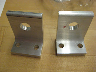
We're changing the mounting process that we're going to use with the pillows in order to make better use of our time.  Previously the plan was to create 3 holes in the base of each pillow, one for a bolt and two for dowel pins.  Since it is going to take too long to get the appropriate precision for the dowel pin holes we are changing the design so each pillow is connected to the base plate via two 1/4-20 bolts.  The current design will look like this:
Front and back pillow

Another component that will be manufactured soon is the base plate.  This will be done on the water jet because it involves lots of holes.  The counter bores for each hole will then be finished on the mill.
Base plate (bottom view to show counterbores)

Finally, a recap of the lessons we learned in the shop this week.  Hopefully this will keep someone else from having these difficulties.

When using the edge finder to zero the x and y co-ordinates after milling a part to size, remember to do two things.  
  1. Take into account the radius of the edge finder itself!  Otherwise measurements will be ~0.1" off.
  2. When re-orienting a part to work on a different aspect of it, remember to re-zero the mill off of the same edge as before!  This edge will likely be in a different location than it was, so be careful.  
That's all for now.  Expect more updates as this week unfolds.

Monday, November 8, 2010

Worm Gear

Good news!  The worm and worm gear came in the mail today.  The teeth aren't as deep as I had expected when I ordered them, but it will still serve it's purpose as long as we are precise in our machining.

Here are some pictures:

The set screws can be seen on the right hand side of each.  They're very small!

Sunday, November 7, 2010

Slot Module Update

After looking at the original pictures of our slot module (see first post) I've decided to upload some more recent screenshots.
Close-up of the slot module chassis
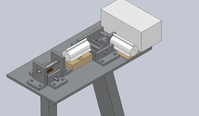
Here's a quick breakdown of slot module changes:  
  • The control box has been located on the back (the big white box) although the fit is a little tight.  
  • The planetary gearboxes have been located as well (the while cylinders); they sit on wooden risers to make proper alignment with the shafts.  Note that the largest wooden riser in this photo may be replaced with an aluminum one (see previous post).
  • The front and back toggle jam arm pillows are now being made out of a larger piece of angle aluminum to eliminate the wooden risers.  See the next picture.
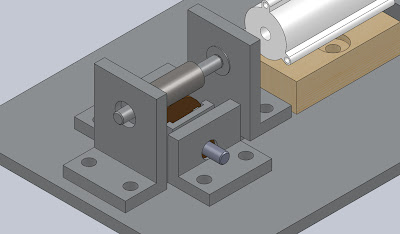
Close of up toggle jam arm pillows
Here the taller front an back pillows are easier to discern.  This ought to be simpler to machine and more accurate over using wooden risers (compare this setup with the original configuration from the first post).  Also in this picture, the worm can be seen as an over sized steel cylinder mounted on the upper shaft.  It contacts the large bronze worm gear that is embedded in the pillow structure.

Another slight modification:  The worm gear is of a larger diameter than the toggle arm is thick, so the upper end of the arm has been cut to allow the gear to protrude from the sides:

The two foreground pillows have been made clear so the inner axle layout and the top end of the toggle arm can be seen.
Notice the bushings on the lower axle and the bearings on the upper.

We'll be heading to the machine shop this week, so expect an update on manufacturing soon!

Saturday, November 6, 2010

MS6 Recap

The engineering for our most critical module turned out well.  We're pleased with our progress so far, but there are some points that we need to take care of looking forward:

1.  Should we replace the wooden toggle arm motor riser with an aluminum block?  In our discussion during MS6 it sounded like the compound wooden block will be challenging to machine.  It may be better to simply buy  an aluminum block of similar dimension and mill it to size.

Breakdown of buying AL versus using wood:
Pros:  Simpler manufacturing
Cons:  Increased cost, possibly increased weight compared to wood.

2.  How will we locate and attach the pillows with the base plate?  There are two options that we are currently considering.

Option one:  Use two bolts for each pillow (this is our current setup).
         Pros:   Simpler to machine, lower tolerances.
         Cons:  Pillows not self-aligning, possibility for "drift" if bolts aren't tight enough.  Poor engineering
                    practice to use threaded fasteners to constrain shear loads.

Option two:  Use two dowels to locate each pillow and a single bolt to hold it down.
         Pros:   Excellent alignment.  Better engineering practice to use dowels to constrain shear loads.
         Cons:  More steps in manufacturing (drilling + reaming).  Slight error in machining could be cause for
                    part rejection.

Dowels pins.  Useful for accurate location of a part.
Source:  


Since machining begins on Monday, we will be making a decision on this in the next few days.  


Thursday, November 4, 2010

Progress up to MS6

We are currently finalizing MS6.  The bill of materials and the manufacturing plan is going well.  A Google doc is proving very useful to allow team collaboration on these documents.

Making the engineering drawings is coming along, but some of the details difficult to nail down.  Certain SolidWorks features (like SmartDimension and title block editing) are finicky and it takes some coercion before the program does what we want of it.

Another issue we're coming up against is tolerancing.  It isn't always clear to us when to use what tolerances, so more reading/research into this subject is needed.  We'll post more as we figure this out.

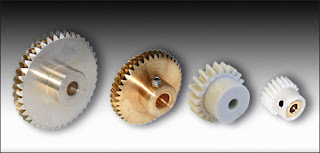
The good news is that our worm and worm gear is in the mail!  The combo gives a 40:1 reduction.  The supplier we used was SDP/SI and we'd definitely buy from them again.  The prices were good (especially compared to McMaster) and there was plenty of variety.  Here are some pictures to give an idea of the parts we ordered (our worm is steel, our gear is bronze):


Tuesday, November 2, 2010

MCM Preparation

For MS6 here are the are the following links:

Step by step manufacturing plan (update as you go):   http://goo.gl/GvlZ

Bill of Materials (update as you go):  http://goo.gl/Bt3X

Tuesday, October 26, 2010

Monday, October 25, 2010

Strategy and Concept Description

Team Strategy:  To score slot balls by getting them past the flipper and to defend against the opponent on the table top.  The ability to score table top balls will also be available in order to adapt to the opponents strategy.

Machine Concept:  Our machine currently has two arms in the main module.  The first arm toggles the flipper with the help of a worm gear and the second arm sweeps balls past the flipper.  Module number two is a bulldozer that can push balls around on the table and interfere with the opponent.  The bulldozer can also cover the opponent's funnel.
Solid Module showing all modules


Close up of worm gearing on main module